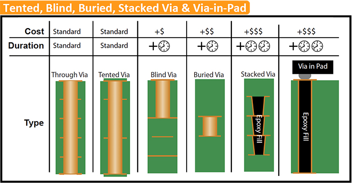

Certain pads for power dissipation use vias in the big pad to conduct the heat away.BGAs may require via-in-pad because there may not be enough space to route the board otherwise.Certain RF applications may need the pad in the via, but then the common practice is to use many vias.If they are careful they will ask you to move the vias out of the pads. If your assembly house makes sloppy work they will let you do this. There shall be at least 100um solder mask between the pad and the via, exactly to avoid this problem. In our design rules I have defined this as no-go.

DIPTRACE TENTED VIAS CRACK
And I have seen such joints crack up after a while, losing contact. I have seen a number of such solder joints. at a major manufacturer of telecom equipment: Don't even think about via-in-pad.

This practice is expressly forbidden in any company taking their work seriously. The solder joint will not have enough solder to be reliable. The solder will suck into the via and create a faulty soldering. I doesn't saw any defect on a batch of 1000 board with more than 40 component like the following figure In both of these cases I had used mechanical drilling with no resin plugged holes. I've had a succesful experience with placing 0603 component (imperial) with 0.3mm via in it and 0402 component (imperial) with 0.2mm vias in it on my board. Via In Pad for Passive Componentsīut all these recommendation are only for the BGA parts, If your pad be big enough and your hole size be small relative to the pad size (like the TI board you mentioned) you don't need any laser drilling nor plugging the vias because it's effect will be too small to be noticable. Moreover in the assembling proccess to avoid sucking out solder paste you need to resin plug these vias too which again cost you more. In this case your manufacturer may recommand to you that use laser drilling instead of mechanical drill and it surely cost you more. Via in pad is a bad thing if your via's hole occupy more than 30% of the pads area AND if your pad is too small too! If your pad be too small and you use mechanical drill this might blow out the pad. To put it short, yes you can but you need a little care along the way. You already asked for the smd pads not BGAs, nevertheless I saw many answers that only cover up for BGAs/ICs fanouts not the passive components. I'm talking with experiences not imaginary recommandation with no actual evidence to back it up. This document discusses various plugging techniques. plating bulging with expansion of plug, or dimpling) The reason it's more expensive is due to the complex process (compared to standard vias) and potential problems (e.g. It's easy to see why the via-in-pad version is preferable for high speed designs that need to keep inductance low. To illustrate the advantage, here is an example of a TQFP footprint fanout with standard vias and via-in-pads: They are also useful for Micro-BGA designs, where space is very limited and traditional fanout techniques cannot be used.Ī via-in-pad (or capped/plated via) is not to be confused with a "tented via", which is a standard via with soldermask covering the hole (hence "tented") You have to check whether your PCB house can do this though, and it may cost more (via will need to be plugged and plated over to provide a smooth surface) If you can't put the via in the pad, putting directly adjacent and using more than one can help reduce inductance. the connection goes straight from pad to plane rather than pad-trace-via-plane) Vias in the pads are useful in high speed designs since they reduce trace length and therefore inductance (i.e.


 0 kommentar(er)
